


Does your rotary axis jog quickly but then when running jobs move much slower than expected? If so this program may be able to help solve that problem!
Download (Windows/Mac/Linux): Rapid Rotary v1.2b (updated: 2 Nov 2017) older version: Rapid Rotary v1.1
Source Code: https://github.com/sgano/RapidRotary
If your g-code is in a different format, are interested in probing routines, or prefer working with python check out this project by McCloud Aero: Rotary Axis CAM Scripts
Video introduction and demonstration:
Background and Problem Description
This program converts G-code from G94 (units per minute feed rate mode) to G93 (Inverse time mode). The main difference between these two modes is that in G93 for every linear or arc move (G1, G2, or G3) that command must also specify how much time it should take to make that move. Using G93 is advantages when a move has both linear as well as rotary components. The reason is because linear moves have units of distance while rotary moves are measured in degrees and many CAM software packages only specify feed rates in the G-code in distance units, for example F90 (in English units) would mean a rate of 90 inches per minute. However, if you had a rotation move at the same time the controller (e.g., LinuxCNC) would interpret that to mean 90 degrees per minute. At this rate it would take 4 minutes to make one complete revolution! That is slow! The solution to this problem is to use inverse time where each move has a specified time to execute which is independent of the units that either axis type uses!
I have not been able to find any hobby or mid-level CAM tools that will output G-code in G93 mode. For indexed strategies where the rotary axis is not used much, this doesn’t pose a big problem. However, for some cases when there are lots of rotary movements the results are so slow that the rotary axis is almost un-useable. People have “gamed” the system by ramping up the feed rates so that the rotary axis moves faster but this also means that the linear axes move much too fast and generally are then capped by their physical maximum speeds. To solve this, issue some controllers (like Mach3 / Mach4) have options to use the z-axis to compensate the rotary axis feed rates by assuming that the Z-0 point is centered on the rotary axis and then convert linear speed to rotational speed using the arc-length of a circle with a radius equal to the current position of the z-axis. But other controllers like LinuxCNC do not offer this option – and that is what is the problem that this program was written to solve.
Summary of what Rapid Rotary does:
This application does not alter any of the positions in the G-code movement commands. It instead converts from G94 to G93 by calculating the distance the tool travels for each line and using the last feed rate specified to calculate the time it should take the tool to complete that movement. For rotary moves the program uses the z-axis position (as the radius value) to convert from rotational units (angles) to distance. This allows for constant tool tip feed rates even for complex geometries and results in slower A-axis rotations when machining larger diameter sections of a part and faster A-axis rotations when machining smaller diameter areas.
The program has an entry field where the user can specify the Z-zero offset from the rotary axis. If this value is 0.0 (default) then the G-code was calculated with the Z-zero point on the rotary axis. If the Z-zero position is on the material surface, then the user should set this offset value to be the radius of the material.
How to use the program:
1) Generate the g-code (.ngc) for your part using your CAM software. Be sure to use a compatible post processor (see the limitations section).
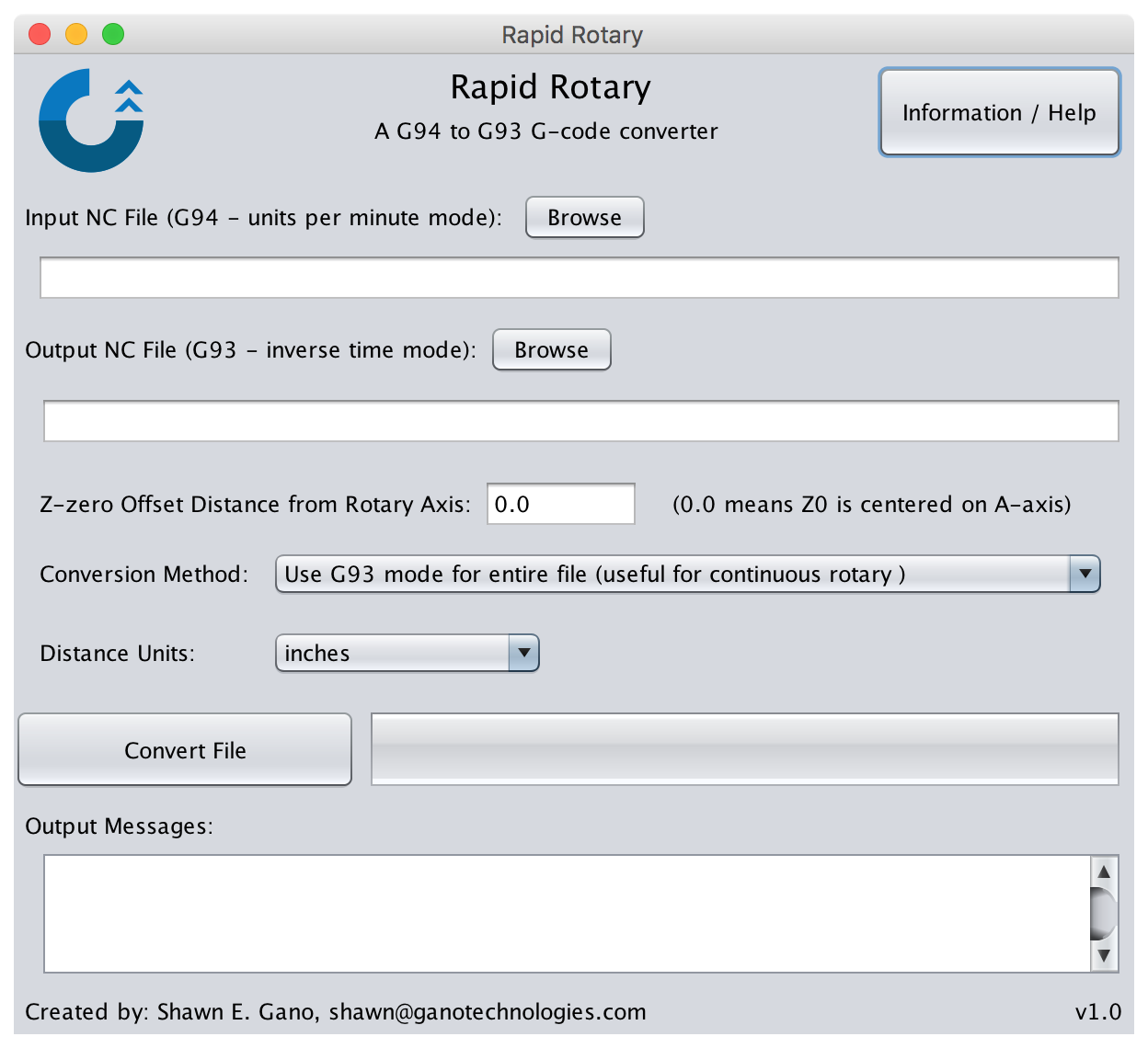
2) Start the Rapid Rotary application, and select the top “Browse” button and locate the file created in step 1. The output file is automatically set with a “_G93” added to the file name which you can change by selecting the second “Browse” button if you want.
3) Set the Z-zero offset value used with modeling the part. If the Z-zero is on the rotary axis then leave the 0.0 (default) value. If the Z-zero is on the surface of the material, then set this value to be the material’s radius.
4) Select a conversion method. Normally this will be the default “Use G93 for the entire file” which is useful when the job has lots of rotary movements. However, if the job only has a few rotational cuts it might be more efficient to wrap each line in G93 instead. In that case choose the second option “Warp each rotary move in G93”.
5) Specify the units for the project in either inches or millimeters (mm). This is mainly used for tolerance and error checking scaling as the majority of the conversion is not reliant on the underlying model units.
6) Finally press the “Convert” button. A summary of the results is displayed in the bottom of the program and if there are any errors and details are also shown.
7) Manually inspect and/or test the output .ngc to be sure that there were no errors or bugs in the conversion process and that it is safe to run on your machine and setup.
What has been tested / verified:
Rapid Rotary has been tested using a couple of example .ngc files created by Vectric’s v8.5 software suite (VCarve/Aspire) using the rotary wrapping feature. The post processors I used for the testing setup are included for reference. Then those output toolpaths were verified to run correctly on a Probotix Nebula machine with a LinuxCNC controller (v2.5). This does not mean that it will work properly for your configuration so be sure to double check the files!
Limitations / requirements / tips and tricks:
- Supports up to four axes (X,Y,Z,A)
- Supports G01, G02, G03 movement commands (G02 and G03 are not typically used in rotary jobs however)
- requires a space between X, Y, Z, A, I, J entities in the G-code (e.g, X0.2Y0.1 is not supported) [this can be configured in your post processor, refer to the example post processor]
- requires the input file use G94 (units per minute feed rate mode) and be specified in the input file
- Requires G17 (plane select: XY), G18 (ZX), or G19 (YZ) to be specified at the start of the input file (supports switching in the file) (G18 and G19 added in V1.2)
- If a comment is found on a line, denoted by '(' the rest of the line is ignored and the comment is copied into the output file